



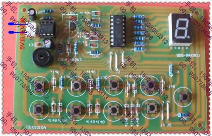
Octal Digital Responder electronic learning kit parts DIY produced teaching experiment Электронные компоненты и - купить
Специальная цена *
Категория товара: Интегральные схемы

История изменения цены
Купить Octal Digital Responder electronic learning kit parts DIY produced teaching experiment | Электронные компоненты и
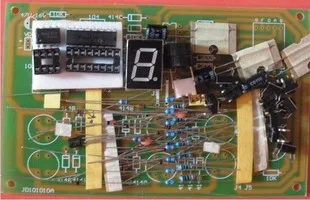
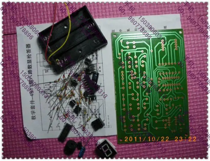
The main purpose of secondary vocational schools Electronic Skills Competition is commonly used to improve the student 's identification and $ element detection capabilities , assembly and welding capabilities of electronic products, basic circuit analysis and application capabilities , while enhancing their electronic products debugging and maintenance capability , the ability to use and operation of the instrument used to detect , and thus stimulate students' interest and so on. Our secondary vocational schools in the training process electronic skills competition , we make a lot of typical small circuit for the high vocational colleges teaching practice .
\u0026 np; \u0026 np; Gold Treasure electronic technology long as we provide opportunities for hands-on practice , and want to experience hands-on installed friend , please hurry to take action
\u0026 Np; \u0026 np; \u0026 np; \u0026 np; \u0026 np; \u0026 np; \u0026 np; \u0026 np; \u0026 np; this issue is a simple and practical number eight significant Responder, including answer, coding, priority latch, digital display, reset, and audio oscillation circuit . Seen from the schematic, the device includes $ CD4511.NE555, IN4148, triode (9 0 1 4), LED common cathode LED, speaker, small button switches and resistors capacitors. Responder digital circuit: J1 ~ J8 eight button switches consisting answer key. D1 ~ D12 twelve diodes encoder will answer in BCD code by pressing the corresponding key is encoded and the resulting high level of added CD4511 corresponding input. CD4511 is a containing BCD - seven segment latch / decoder / driver circuit in one of the integrated circuit. CD4511 of 1,2,6,7 feet to BCD inputs, 9 to 15 feet for the display output. 3 feet for the test side (LT), when LT is \"0\", the output of all \"1.\" 4 feet for blanking end (BI), when BI is \"0\", the output of all \"0\", so then you can clear the value latch inside, you can use the reset terminal. 5 allows the latch pin end (LE), when LE end by \"0\" → \"1\" when, a, b, c, d, e, f, seven outputs are held in the LE is \"0\" when plus BCD code corresponding digital display. 16,8 feet respectively connected to the power of positive and negative. By CD4511 pin diagram shows, 6, 2, 1, 7 feet represent 8,4,2,1 bit BCD code. Press the corresponding button, you can get a series of eight 0001,0010,0011,0100,0101,0110,0111,1000 BCD code. CD4511 high is placed on the corresponding input of the internal circuit can be decoded by a decimal number displayed on the digital tube. Priority latch circuit composed of two diodes (D13, D14), a transistor (VT), two resistors and CD4511 latches allow the end (LE) is completed. When the initial state or the state after reset, CD4511 input terminal is associated with a resistor (10K) connected in series to ground, so in this case the BCD input is \"0000\", the CD4511 output terminals a, b, c, d, e, f are high, is low, and the digital display is \"0.\" And when d is high, the transistor (VT) is turned on and is low, D13, D14 cathode are low, so that end CD4511 LE is low level \"0\", can be seen at this time no latch which allows BCD code input. And when any one answer key is pressed, the digital display shows, CD4511 the output d output is low or output output is high, the two states must have a presence or significant are present. Forcing CD4511 the LE terminal, and \"0\" → latched digital \"1\", BCD code about to enter the first display and keep. At the moment, the other key code can not be entered, so as to achieve the purpose of the answer. Multivibrator NE555 audio oscillator circuit is composed of promoting sound speakers hearing. Four diodes (IN4148) consisting of diodes or gates, respectively, then the 1,2,6,7 CD4511 pin provides power for the NE555 + Ucc, when any answer that key is pressed, the speaker can be issued for parts of the board ( Suite), all new original $ device is not the finished board, oh, the buyer must have a certain electronic infrastructure and ability, that there is no basis for buyers buy with caution. Because the parts, once sold, refused to return, also please your receipt when the courier unpacking, abnormal, please make a record and signed by courier to post claims \u0026 hell; \u0026 hell;
( 10,259,316,114 ) ( 58,896,530 )Отзывы о Octal Digital Responder electronic learning kit parts DIY produced teaching experiment Электронные компоненты и
Здесь вы можете оставить свой отзыв о данном товаре.